
Solenoid Valve Working Principle Types Components and Troubleshooting Guide
A solenoid valve is often a small item in a plant, but when it fails, the fault can stop a packaging line, flood a skid, starve a burner, or keep a pneumatic actuator from moving. The good news is that most solenoid valve problems follow a clear pattern once the working principle is understood.
At its simplest, a solenoid valve uses an electrical coil to move a metal plunger. That movement opens or closes a path for air, water, steam, oil, gas, or another fluid. In practice, the details matter. A direct-acting valve behaves very differently from a pilot-operated valve. A normally closed valve fails in a different state from a normally open one. A coil fault can look like a mechanical jam if it is not checked properly.
This guide explains the solenoid valve working principle, main types, key components, common failure modes, and practical troubleshooting steps for plant maintenance teams.

How a solenoid valve works
A solenoid valve converts electrical energy into mechanical movement. The main electrical part is the coil, a winding of copper wire. When voltage is applied to the coil, it creates a magnetic field. This field pulls a ferromagnetic plunger or armature against a spring force.
That plunger movement opens or closes an orifice inside the valve body. The orifice is the controlled flow path. When the plunger seals against the seat, flow stops. When it lifts away, flow passes.
The basic sequence is simple:
The control system sends voltage to the coil.
The coil creates a magnetic field.
The plunger moves.
The seal position changes.
The valve opens or closes the fluid path.
When power is removed, the magnetic field collapses. A spring returns the plunger to its original position, unless the valve is a latching design.
In a plant, the coil may be energised by a PLC output, relay, timer, pressure switch, level controller, safety circuit, or local push button. The valve may control compressed air to a cylinder, water to a washing system, steam to a heat exchanger, fuel gas to a burner train, or chemical dosing to a process tank.
A key point for maintenance is that an electrical command does not always mean fluid movement. The coil may energise, but the valve can still fail to open because of low supply pressure, blocked pilot passages, incorrect pressure differential, debris under the seat, swollen seals, or a stuck plunger.
Main components and what they do
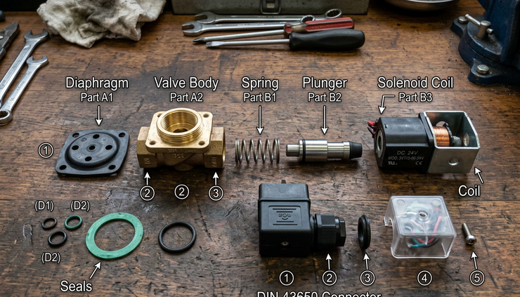
Most industrial solenoid valves contain the same core parts, though the layout changes by size, media, and valve type.
Component | Function | Common maintenance concern |
Coil | Creates the magnetic field that moves the plunger | Burnout, wrong voltage, water ingress, loose connector |
Plunger or armature | Moves when the coil is energised | Sticking due to dirt, corrosion, scaling, or wear |
Spring | Returns the plunger when power is removed | Weakness, breakage, wrong assembly after overhaul |
Orifice | Main opening through which fluid passes | Blockage, erosion, wrong sizing |
Seat and seal | Stops leakage when the valve is closed | Damage, swelling, hardening, chemical attack |
Valve body | Holds pressure and connects to pipework | Cracks, incorrect material, thread damage |
Diaphragm or piston | Helps open larger pilot-operated valves | Tear, stiffness, blocked bleed hole |
Pilot passage | Uses pressure to operate the main diaphragm | Choking from rust, scale, PTFE tape, sludge |
Manual override | Allows local testing without electrical command | Left in override position, broken mechanism |
Electrical connector | Brings power to the coil | Loose terminals, moisture, wrong cable gland |
Body materials usually include brass, stainless steel, aluminium, plastic, or specialised alloys. Seal materials may include NBR, EPDM, FKM, PTFE, or other compounds. Selection depends on temperature, fluid, pressure, and chemical compatibility.
For water, air, and many general services, brass and NBR may be common. For corrosive chemicals or hygienic applications, stainless steel and compatible elastomers may be needed. For steam, high-temperature seals and suitable body design are essential.
Direct-acting and pilot-operated valves behave differently
The two most common operating designs are direct-acting and pilot-operated. Choosing the wrong one can cause repeat failures even when the valve is new.
Direct-acting valves
In a direct-acting solenoid valve, the plunger directly opens or closes the main orifice. The coil force acts straight on the sealing element.
This design has one major advantage: it can work at zero differential pressure. That means the valve does not need upstream pressure to help it open. It is suitable for low-pressure, vacuum, drain, dosing, and vent applications.
Direct-acting valves are usually used where:
Flow is relatively low
The orifice size is small
Pressure differential may be low or zero
Fast response is needed
The process cannot rely on line pressure to assist the valve
The trade-off is coil size and power. A larger orifice requires more force to open against pressure. That makes direct-acting valves less practical for high-flow lines unless the valve is specially designed.
Common direct-acting applications include instrument air bleed lines, analyser sample systems, small water feeds, chemical dosing, burner pilot lines, and vacuum control.
Pilot-operated valves
A pilot-operated solenoid valve uses the coil to open a small pilot passage. The main valve opens because of pressure difference across a diaphragm or piston. The coil does not lift the full main flow area directly.
This design allows high flow with a relatively small coil. It suits larger pipe sizes and higher-flow utilities such as compressed air headers, water lines, irrigation systems, and some process services.
Pilot-operated valves usually need a minimum pressure differential between inlet and outlet. If pressure difference is too low, the valve may not open fully, may chatter, or may not close properly.
They are a poor choice for some gravity-fed tanks, low-pressure transfer lines, closed-loop systems with little pressure drop, and services where the downstream line quickly equalises pressure.
Pilot-operated valves are also more sensitive to contamination. Dirt, rust, scale, or fragments of thread tape can block the pilot hole. A blocked pilot path can make the valve look electrically healthy while the main valve stays shut.
Semi-direct or assisted-lift valves
Some valves combine both ideas. A semi-direct, assisted-lift, or hung-diaphragm valve has a mechanical link between plunger and diaphragm. It can often operate at zero or low differential pressure while still handling more flow than a small direct-acting valve.
These valves are useful where pressure conditions vary. They cost more than basic designs, but they can solve troublesome low-pressure applications.
Feature | Direct-acting valve | Pilot-operated valve |
Needs pressure differential | No | Usually yes |
Flow capacity | Lower | Higher |
Coil power for same size | Higher | Lower |
Dirt sensitivity | Moderate | Higher |
Low-pressure service | Good | Often poor |
Common fault pattern | Stuck plunger or burnt coil | Blocked pilot passage or diaphragm issue |
Normally closed and normally open positions matter
A solenoid valve’s normal position is its state when the coil has no power.
A normally closed valve stays shut when de-energised. It opens only when the coil receives voltage. This is the most common arrangement for water, air, fuel, chemical, and utility control because it stops flow during power loss.
A normally open valve stays open when de-energised. It closes when the coil receives voltage. This is used when flow or venting must continue during power failure, or where energising the coil is only needed to stop flow.
The choice is not just a control preference. It is a safety decision.
Use normally closed when loss of power should stop the process fluid. Examples include:
Fuel gas isolation
Chemical feed shut-off
Water filling valves
Air supply to an actuator that should retract or stop
Use normally open when loss of power should allow flow or release pressure. Examples include:
Cooling water fail-open service
Vent lines that must open on power loss
Air purge lines where flow is safer than shut-off
Dump or drain paths in selected safety designs
Some systems use three-way solenoid valves. These are common in pneumatics. A three-way valve may supply air to an actuator in one state and exhaust it in the other. In maintenance work, check the port markings carefully. Inlet, outlet, and exhaust ports are easy to swap during replacement if the body pattern looks similar.
Latching solenoid valves are another variation. They hold position after a short electrical pulse and do not need continuous coil power. These are useful for battery systems or heat reduction, but troubleshooting needs care because the valve state may not match the present power state.

Coil failure and electrical faults
Solenoid coil problems are common, but they are often misdiagnosed. A coil can fail open circuit, short circuit, overheat, hum loudly, or lose magnetic strength due to poor supply conditions.
Before testing, isolate the equipment, depressurise the line where required, and follow the site lockout procedure. Solenoid valves can move suddenly when energised.
Signs of coil failure
A failed or failing coil may show these symptoms:
No click when energised
Valve body remains in the de-energised state
Coil feels excessively hot
Burnt smell or discoloured encapsulation
Repeated fuse blowing or output trip
Loud humming in AC coils
Intermittent operation when the cable is moved
Water inside the connector or terminal box
A warm coil is not always faulty. Many continuously rated coils run hot to the touch during normal service. The issue is excessive heat, burning, swelling, cracked insulation, or repeated failure.
Common causes of coil burnout
Wrong voltage is a frequent cause. A 24 V DC coil connected to 230 V AC will fail quickly. A 230 V AC coil supplied with low voltage may buzz and fail to pull the plunger fully in. That can overheat the coil.
AC and DC coils are not freely interchangeable. They differ in winding design and magnetic behaviour. AC coils often use a shading ring to reduce chatter. If the shading ring is damaged or dirty, the coil may hum.
Other common causes include:
Coil energised without the correct armature in place
Plunger stuck, preventing full magnetic pull-in
Continuous energising of an intermittently rated coil
High ambient temperature near ovens, boilers, or steam lines
Moisture entering through loose cable glands
Oversized upstream pressure holding the valve shut
Voltage drop across a long cable run
Faulty PLC output, relay contact, or loose neutral connection
Basic electrical checks
Start with the simplest checks.
Check the nameplate. Confirm voltage, AC or DC rating, frequency for AC coils, duty rating, enclosure rating, and manufacturer part number.
Measure voltage at the coil terminals while the coil is connected and commanded on. No-load voltage can look normal even when a cable, relay, or terminal collapses under load.
Measure coil resistance after isolating power. Compare with a known good coil of the same type or the manufacturer’s data. An infinite reading suggests an open winding. A much lower than expected reading suggests shorted turns.
Inspect the plug connector. DIN connectors and moulded plugs often fail due to water ingress, loose screws, damaged gaskets, or incorrect cable glands. In outdoor and washdown areas, connector sealing is just as important as coil rating.
Troubleshooting scenarios from plant maintenance
The fastest way to troubleshoot a solenoid valve is to split the fault into three areas: electrical command, mechanical movement, and fluid conditions. Do not replace the valve until all three are checked.
The PLC output is on but the valve does not open
This is common on compressed air and water skids.
Check for voltage at the coil terminals. If voltage is missing, trace the circuit back through the PLC output, relay, fuse, interlock, emergency stop loop, terminal block, and neutral or negative return.
If voltage is present, listen for a click. A click suggests the coil and plunger are moving. No click suggests a failed coil, stuck plunger, wrong voltage, low voltage, or mechanical binding.
If the coil clicks but flow does not start, check isolation valves, upstream pressure, strainer blockage, downstream blockage, and correct flow direction. Many solenoid valves have a flow arrow. Reversing the valve can prevent proper sealing or opening.
For pilot-operated valves, confirm minimum differential pressure. A valve installed on a tank outlet with little head pressure may never open fully, even though the coil is healthy.
The valve opens but flow is weak
Weak flow usually points to pressure, sizing, blockage, or partial opening.
Check the upstream strainer first. Rust flakes from old pipework often collect there. Next, check the inlet pressure under flow, not only static pressure. A small feed line may show good static pressure and then collapse when the valve opens.
Check whether the valve is undersized. Pipe size and valve flow capacity are not the same. A 25 mm valve body can still have a restrictive orifice. Use the manufacturer’s Kv or Cv data for selection.
If the valve is pilot-operated, inspect the diaphragm and pilot hole. A stiff diaphragm, blocked bleed hole, or torn membrane can cause slow or weak opening.
The valve leaks when closed
Internal leakage usually comes from the seat area. Dirt, scale, PTFE tape, weld slag, hardened deposits, or seal damage can keep the valve from seating.
Isolate and depressurise the line before opening the valve. Inspect the seat and seal. Clean the parts with a method suitable for the valve material and process media. Do not scratch a soft seat with a sharp tool.
Check back pressure and flow direction. Some valves cannot seal properly if installed backwards. Also confirm that the valve is suitable for the pressure. Excess pressure can damage the seat or keep the valve from closing.
In steam service, leakage can worsen after water hammer or poor condensate removal. Steam valves need proper warm-up, drainage, and high-temperature sealing materials.
The valve chatters or hums
A light hum from an AC coil can be normal. Loud chatter is not.
Electrical causes include low voltage, wrong frequency, loose connector, damaged shading ring, or poor earthing where applicable. Mechanical causes include dirt on the plunger, wear in the guide tube, or foreign material preventing full seating.
Fluid causes are just as likely. A pilot-operated valve can chatter if the pressure differential is near the minimum required value. Pump pulsation, unstable regulator pressure, or rapid downstream pressure changes can also make the valve oscillate.
Fit a pressure gauge upstream and downstream during the fault. Many chatter problems become clear when pressure is observed during operation.
Coils keep burning out after replacement
Repeated coil burnout means the coil is usually the victim, not the root cause.
Check voltage and type first. Confirm the replacement coil exactly matches the original rating. Then check whether the plunger moves freely. If the armature cannot complete its stroke, the coil may overheat.
Look at ambient heat. A coil beside a steam line, furnace, or hot enclosure may exceed its thermal rating. Also check whether the valve is energised continuously while using a coil meant for intermittent duty.
Moisture is another common cause. In washdown areas, fit the correct connector gasket, cable gland, and IP-rated coil. Route the cable so water does not run down into the connector.

How to select the right solenoid valve
A reliable valve starts with correct selection. Replacing like-for-like is not always enough, especially if the process has changed.
Check these points before ordering or installing a valve:
Fluid compatibility
Confirm the body, seal, diaphragm, and internal materials suit the media. Air, potable water, steam, diesel, caustic, solvents, and acids need different materials.
Pressure range and pressure differential
Check both maximum pressure and minimum pressure differential. Direct-acting valves handle zero differential better. Pilot-operated valves need enough pressure drop to function.
Flow requirement
Use Kv or Cv values, not only pipe size. Undersized valves cause low flow and pressure drop. Oversized valves can cycle poorly in some control duties.
Temperature
Consider media temperature and ambient temperature. Steam, hot water, and outdoor installations in India can stress coils and seals.
Voltage and control system
Match AC or DC supply, voltage, frequency, duty cycle, connector type, and PLC output capacity. Add surge suppression where the control design requires it, especially for DC coils switched by electronic outputs.
Fail-safe position
Choose normally closed or normally open based on the safest state during power loss. For critical services, review this with the process and safety requirements.
Environment
For washdown, dust, rain, chemical vapour, or hazardous areas, choose the correct enclosure and approvals. A standard indoor coil may not survive outdoors near a cooling tower or chemical dosing skid.
Maintenance access
Leave enough space to remove the coil, connector, strainer, and top assembly. Fit upstream filtration where dirt is expected. Add isolation valves where safe and permitted so maintenance does not require draining a large header.
A simple plant rule helps: if the valve fails repeatedly, review the application, not only the part number. Many repeat solenoid failures trace back to dirty media, heat, poor voltage, wrong valve type, or missing pressure differential.
A practical takeaway for maintenance teams
A solenoid valve fault rarely needs guesswork. Start with the normal state, then confirm the command signal, coil health, mechanical movement, pressure conditions, and flow path. Treat direct-acting and pilot-operated valves differently, because they fail for different reasons.
For critical plant services, keep records of coil voltage, valve type, seal material, pressure range, and failure history. Stocking one “similar” valve for every duty can create more downtime than it saves.
The best troubleshooting habit is simple: prove whether the problem is electrical, mechanical, or process-related before replacing parts. That approach reduces repeat failures, protects the system, and gets the plant running with fewer surprises.


Comments